
think…mercer first®
Features:
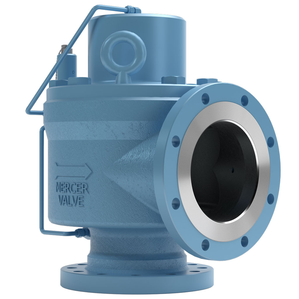
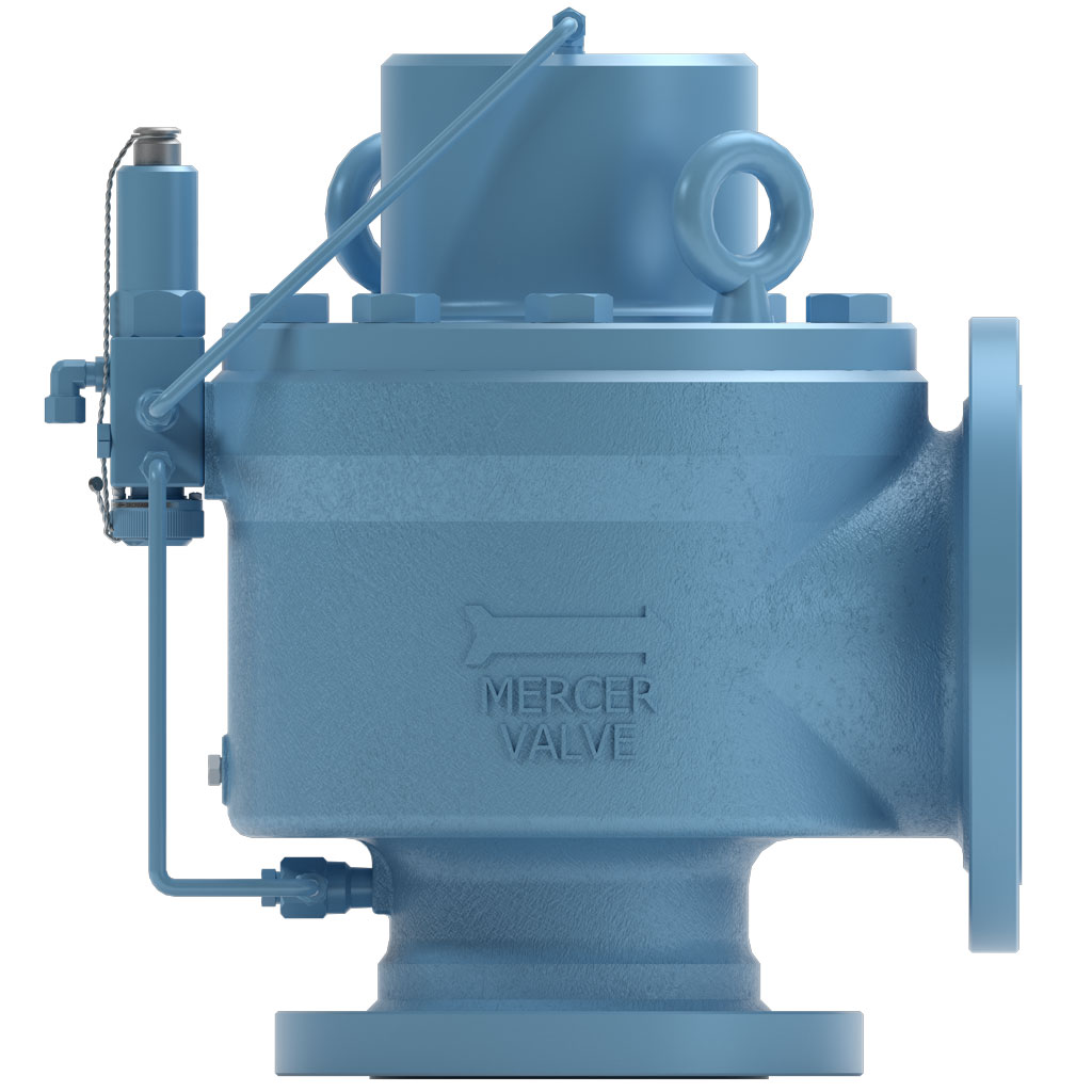
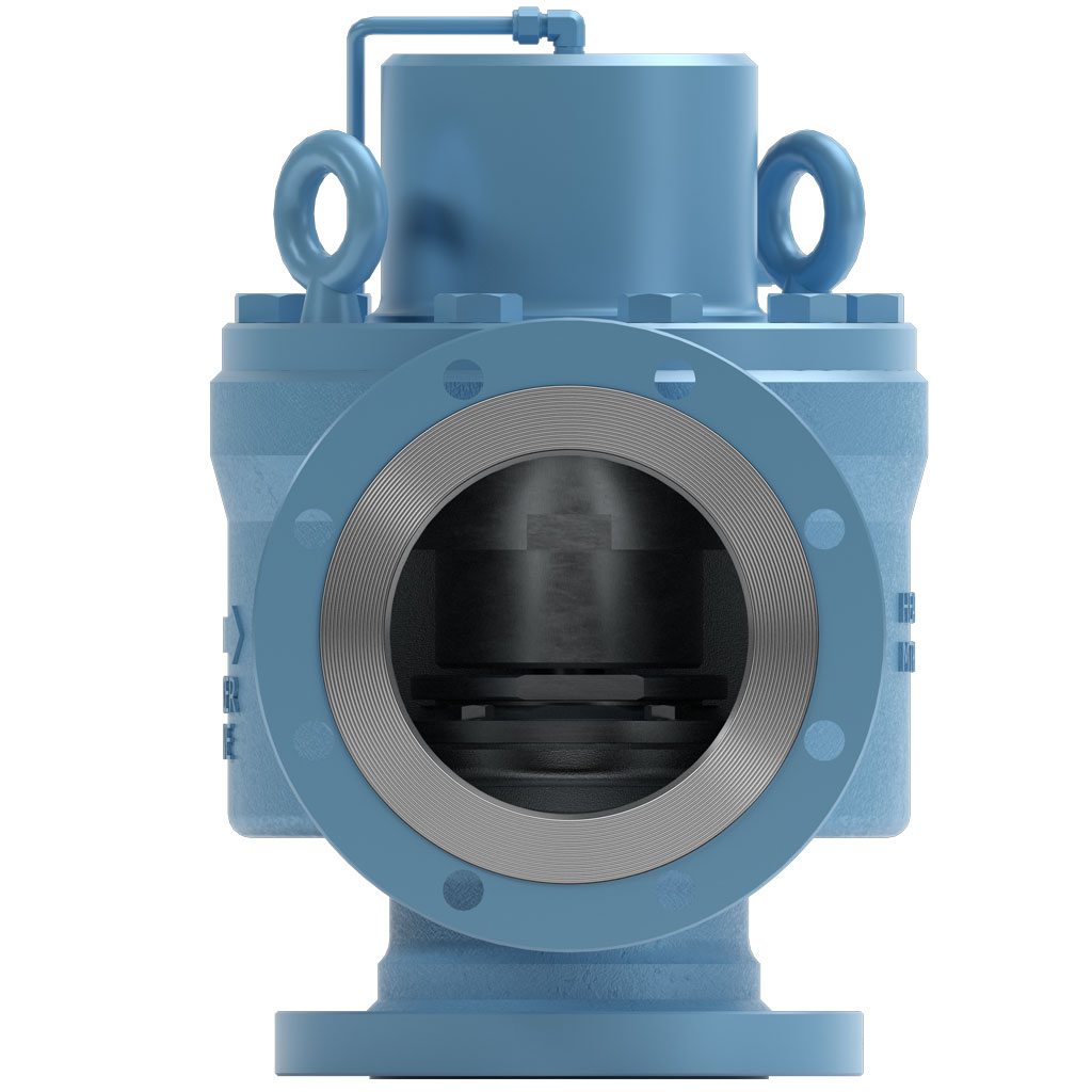
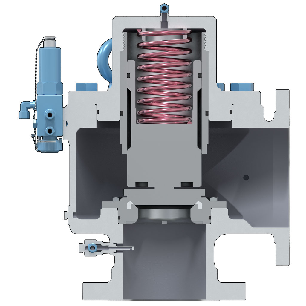
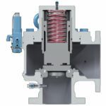
- Designed with "Auto Seat Technology"®
- A low rated and fully guided spring allows for more consistent Set Pressures from pop to pop.
- Consistent Set Pressures allows for repeatable use without the need for excessive repairs or resetting.
- Open, Close, Seat and Seal™
- Non-rising stems allowing valves to be installed in small areas.
- Pilot Valve options include: Backflow Preventer, Pressure Snubber and Auxiliary Filter.
- Snap Pilot Valve options include: Field Test Connection, Test Gag, and Manual or Remote Blowdown.
- Sour Service Trim available.
- Additional options available to meet NACE MR0175 requirements.
- Canadian Registration Number (CRN)
- Additional options available to meet Conformité Européenne (CE) to PED Directive 2014/68/EU and/or ATEX Directive 2014/34/EU
| Orifice | R (USC) | R (SI) |
|---|---|---|
| OrificeStandard Inlet Sizes | R (USC) 6" | R (SI) DN 150 |
| OrificeInlet and Outlet Connection Types | R (USC) RF x RF, RTJ x RF, RTJ x RTJ | R (SI) RF x RF, RTJ x RF, RTJ x RTJ |
| OrificeActual Orifice Diameter | R (USC) 4.750 in | R (SI) 120.7 mm |
| OrificeActual Orifice Area | R (USC) 17.721 in2 | R (SI) 11432.9 mm2 |
| OrificeAPI Orifice Area | R (USC) 16.000 in2 | R (SI) 10322.6 mm2 |
| OrificePressure Range | R (USC) 7.5 – 1480 psig | R (SI) 51 – 10204 kPa |
| OrificeStandard Temperature Range | R (USC) -20°F to 400°F | R (SI) -29°C to 204°C |
| OrificeASME Flow Coefficient, Kd (Gas) | R (USC) 0.870 | R (SI) 0.870 |
Mercer Valve Co., Inc. reserves the right to change product designs and specifications without notice.
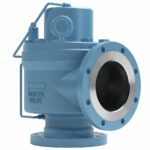
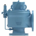
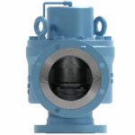
9500 Snap Main Valve "R" Orifice | Part Number Selection
A | INLET & OUTLET COMBINATION
B | API ORIFICE SIZE
C | FLANGE TYPE
D | BODY MATERIAL
E | OPTIONS
F | SEAT MATERIAL
G | SOUR GAS SERVICE
H | PILOT TYPE
I | O-RING MATERIAL┼┼
J | TWO-DIGIT "SPECIAL" CODE
★Standard Materials or Options.
┼┼O-ring codes are only used with Seat codes 7, 9, & Y when O-rings are not standard FKM. If using the standard FKM O-rings, leave O-ring code BLANK.
9500 Snap Pilot Valve | Part Number Selection
A | BODY / BONNET MATERIAL
B | UPPER SEAT / LOWER SEAT▽
C | BLOWDOWN TYPE
D | FIELD TEST CONNECTION
E | TEST ACCESSORIES
F | SPRING CODE
G | SOUR GAS SERVICE
H | ORING MATERIAL▽
I | TWO-DIGIT "SPECIAL" CODE
★Standard Materials or Options.
▽Seat and O-Ring Material codes must match when available. Consult Factory.
╋May require a Special Code on the Main Valve. Consult Factory.
| Inlet and Outlet Code | Inlet and Outlet Size (in) | Pressure Limit 1, 2 (psig) | Dimensions 2 "A" x "B" x "C" (in ± .125) | Approximate Weight 2 (lbs) |
|---|---|---|---|---|
| Inlet and Outlet Code76☆ | Inlet and Outlet Size (in) 6" 150 x 8" 150 | Pressure Limit 1, 2 (psig)285 | Dimensions 2 "A" x "B" x "C" (in ± .125) 9.438 x 9.500 x 22.829 | Approximate Weight 2 (lbs) 420 |
| Inlet and Outlet Code77☆ | Inlet and Outlet Size (in) 6" 300 x 8" 150 | Pressure Limit 1, 2 (psig)740 | Dimensions 2 "A" x "B" x "C" (in ± .125) 9.438 x 9.500 x 22.829 | Approximate Weight 2 (lbs) 435 |
| Inlet and Outlet Code78☆ | Inlet and Outlet Size (in) 6" 600 x 8" 150 | Pressure Limit 1, 2 (psig)1020 | Dimensions 2 "A" x "B" x "C" (in ± .125) 9.688 x 9.500 x 23.016 | Approximate Weight 2 (lbs) 460 |
| Inlet and Outlet Code76X | Inlet and Outlet Size (in) 6" 150 x 8" 150 x 8" 150 | Pressure Limit 1, 2 (psig)285 | Dimensions 2 "A" x "B" x "C" (in ± .125) 9.438 x 9.500 x 9.500 x 22.829 | Approximate Weight 2 (lbs) 430 |
| Inlet and Outlet Code77X | Inlet and Outlet Size (in) 6" 300 x 8" 150 x 8" 150 | Pressure Limit 1, 2 (psig)740 | Dimensions 2 "A" x "B" x "C" (in ± .125) 9.438 x 9.500 x 9.500 x 22.829 | Approximate Weight 2 (lbs) 445 |
| Inlet and Outlet Code78X | Inlet and Outlet Size (in) 6" 600 x 8" 150 x 8" 150 | Pressure Limit 1, 2 (psig)1020 | Dimensions 2 "A" x "B" x "C" (in ± .125) 9.688 x 9.500 x 9.500 x 23.141 | Approximate Weight 2 (lbs) 470 |
| Inlet and Outlet Code79X | Inlet and Outlet Size (in) 6" 600 x 8" 300 x 8" 300 | Pressure Limit 1, 2 (psig)1480 | Dimensions 2 "A" x "B" x "C" (in ± .125) 9.688 x 10.438 x 10.438 x 23.141 | Approximate Weight 2 (lbs) |
1 Pressure limit may be subject to system conditions and temperatures.
2 Pressure limit, weight, and “C” dimension may vary with sour gas service.
★ Flange centerline to face dimensions compliant with API 526.
| Inlet and Outlet Code | Inlet and Outlet Size DN (mm) | Pressure Limit 1, 2 (kPa) | Dimensions 2 "A" x "B" x "C" (mm ± 3.175) | Approximate Weight 2 (kg) |
|---|---|---|---|---|
| Inlet and Outlet Code76☆ | Inlet and Outlet Size DN (mm)DN 150 150 x DN 200 150 | Pressure Limit 1, 2 (kPa)1965 | Dimensions 2 "A" x "B" x "C" (mm ± 3.175)239.7 x 241.3 x 574.7 | Approximate Weight 2 (kg)190.5 |
| Inlet and Outlet Code77☆ | Inlet and Outlet Size DN (mm)DN 150 300 x DN 200 150 | Pressure Limit 1, 2 (kPa)5102 | Dimensions 2 "A" x "B" x "C" (mm ± 3.175)239.7 x 241.3 x 574.7 | Approximate Weight 2 (kg)197.3 |
| Inlet and Outlet Code78☆ | Inlet and Outlet Size DN (mm)DN 150 600 x DN 200 150 | Pressure Limit 1, 2 (kPa)7032 | Dimensions 2 "A" x "B" x "C" (mm ± 3.175)246.1 x 241.6 x 793.8 | Approximate Weight 2 (kg)208.7 |
| Inlet and Outlet Code76X | Inlet and Outlet Size DN (mm)DN 150 150 x DN 200 150 x DN 200 150 | Pressure Limit 1, 2 (kPa)1965 | Dimensions 2 "A" x "B" x "C" (mm ± 3.175)239.7 x 241.3 x 241.3 x 574.7 | Approximate Weight 2 (kg)195.0 |
| Inlet and Outlet Code77X | Inlet and Outlet Size DN (mm)DN 150 300 x DN 200 150 x DN 200 150 | Pressure Limit 1, 2 (kPa)5102 | Dimensions 2 "A" x "B" x "C" (mm ± 3.175)239.7 x 241.3 x 241.3 x 574.7 | Approximate Weight 2 (kg)201.8 |
| Inlet and Outlet Code78X | Inlet and Outlet Size DN (mm)DN 150 600 x DN 200 150 x DN 200 150 | Pressure Limit 1, 2 (kPa)7032 | Dimensions 2 "A" x "B" x "C" (mm ± 3.175)246.1 x 241.3 x 241.3 x 581.0 | Approximate Weight 2 (kg)213.2 |
| Inlet and Outlet Code79X | Inlet and Outlet Size DN (mm)DN 150 600 x DN 200 300 x DN 200 300 | Pressure Limit 1, 2 (kPa)10204 | Dimensions 2 "A" x "B" x "C" (mm ± 3.175)246.1 x 256.2 x 256.2 x 793.8 | Approximate Weight 2 (kg) |
1 Pressure limit may be subject to system conditions and temperatures.
2 Pressure limit, weight, and “C” dimension may vary with sour gas service.
★ Flange centerline to face dimensions compliant with API 526.