
think…mercer first®

Features:
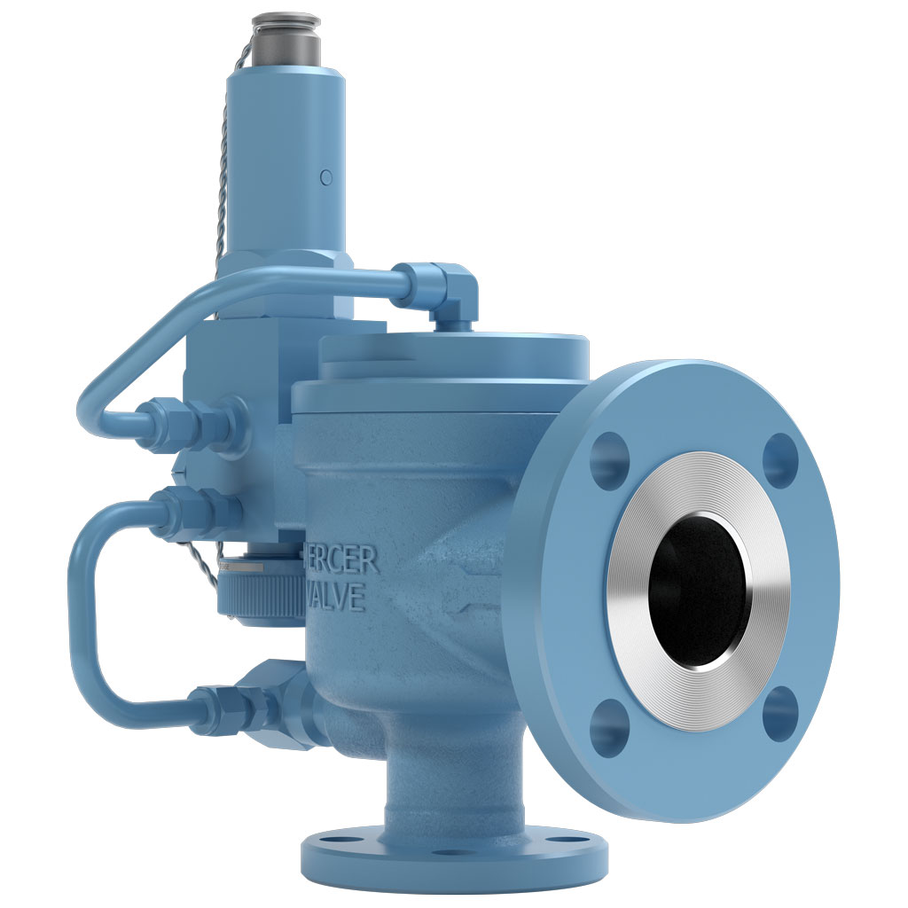
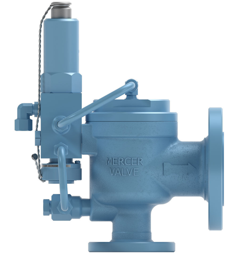
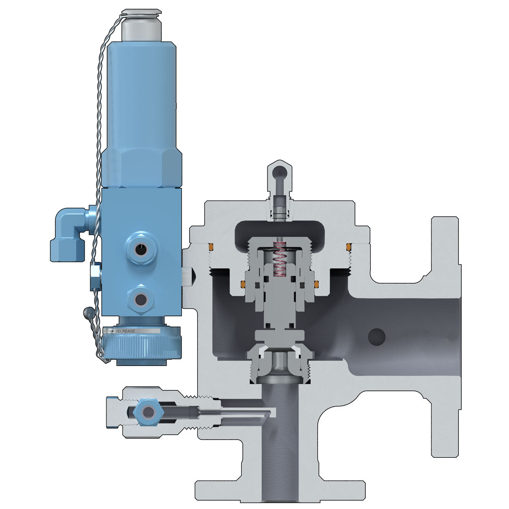
- Designed with "Auto Seat Technology"®
- A low rated and fully guided spring allows for more consistent Set Pressures from pop to pop.
- Consistent Set Pressures allows for repeatable use without the need for excessive repairs or resetting.
- Open, Close, Seat and Seal™
- Non-rising stems allowing valves to be installed in small areas.
- Pilot Valve options include: Backflow Preventer, Pressure Snubber and Auxiliary Filter.
- Snap Pilot Valve options include: Field Test Connection, Test Gag, and Manual or Remote Blowdown.
- Sour Service Trim available.
- Additional options available to meet NACE MR0175 requirements.
- Canadian Registration Number (CRN)
- Additional options available to meet Conformité Européenne (CE) to PED Directive 2014/68/EU and/or ATEX Directive 2014/34/EU
| Orifice | 1 1⁄2" FB (USC) | 1 1⁄2" FB (SI) |
|---|---|---|
| OrificeStandard Inlet Sizes | 1 1⁄2" FB (USC) 1 1⁄2" | 1 1⁄2" FB (SI) DN 40 |
| OrificeInlet and Outlet Connection Types | 1 1⁄2" FB (USC) RF x RF, RTJ x RF, RTJ x RTJ | 1 1⁄2" FB (SI) RF x RF, RTJ x RF, RTJ x RTJ |
| OrificeActual Orifice Diameter | 1 1⁄2" FB (USC) 1.500 in | 1 1⁄2" FB (SI) 38.1 mm |
| OrificeActual Orifice Area | 1 1⁄2" FB (USC) 1.767 in2 | 1 1⁄2" FB (SI) 1140.0 mm2 |
| OrificePressure Range | 1 1⁄2" FB (USC) 15 – 2500 psig | 1 1⁄2" FB (SI) 104 – 17236 kPa |
| OrificeStandard Temperature Range | 1 1⁄2" FB (USC) -20°F to 400°F | 1 1⁄2" FB (SI) -29°C to 204°C |
| OrificeASME Flow Coefficient, Kd (Gas) | 1 1⁄2" FB (USC) 0.870 | 1 1⁄2" FB (SI) 0.870 |
Mercer Valve Co., Inc. reserves the right to change product designs and specifications without notice.
9500 Snap Main Valve 1-1/2" Full Bore | Part Number Selection
95 -
33
A
1
B
1
C
3
D
0
E
7
F
G
S
H
I
J
A | INLET & OUTLET COMBINATION
(See Dimensions & Weights, below.)
B | ORIFICE SIZE
1 – 1-1/2" FULL BORE – 1.767 in²
C | FLANGE TYPE
1★ – RF x RF
2 – RTJ x RTJ
3 – RTJ x RF
D | BODY MATERIAL
3★ – WCB CARBON STEEL
4 – CF3M STAINLESS STEEL
5 – LCC CARBON STEEL
E | OPTIONS
0★ – NO OPTIONS
1 – BACKFLOW PREVENTER
2 – PRESSURE SNUBBER
3 – AUXILIARY FILTER
4 – OPTIONS 1 & 2
5 – OPTIONS 1 & 3
6 – OPTIONS 2 & 3
7 – OPTIONS 1, 2, & 3
F | SEAT MATERIAL┼┼
7★ – PTFE
8★ – FKM
9★ – PEEK
N – NEOPRENE
B – BUNA
E – EPDM
Y – VESPEL®
G | SOUR GAS SERVICE
BLANK★ - NON SOUR APPLICATIONS
N – SOUR GAS SERVICE
H | PILOT TYPE
S★ – SNAP PILOT (See below for part numbering breakdown.)
I | O-RING MATERIAL┼┼
BLANK★ – STANDARD IF APPLICABLE
3 – PC BUNA
5 – LOW TEMP BUNA
6 – FFKM
7 – FKM ED
9 – NEOPRENE
C – EPDM
K – HNBR
J | TWO-DIGIT "SPECIAL" CODE
(Two-digit special codes assigned by Mercer Valve, if applicable.)
★Standard Materials or Options.
┼┼O-ring codes are only used with Seat codes 7, 9, & Y when O-rings are not standard FKM. If using the standard FKM O-rings, leave O-ring code BLANK.
A | INLET & OUTLET COMBINATION
B | ORIFICE SIZE
C | FLANGE TYPE
D | BODY MATERIAL
E | OPTIONS
F | SEAT MATERIAL┼┼
G | SOUR GAS SERVICE
H | PILOT TYPE
I | O-RING MATERIAL┼┼
J | TWO-DIGIT "SPECIAL" CODE
★Standard Materials or Options.
┼┼O-ring codes are only used with Seat codes 7, 9, & Y when O-rings are not standard FKM. If using the standard FKM O-rings, leave O-ring code BLANK.
9500 Snap Pilot Valve | Part Number Selection
A | BODY / BONNET MATERIAL
B | UPPER SEAT / LOWER SEAT▽
C | BLOWDOWN TYPE
D | FIELD TEST CONNECTION
E | TEST ACCESSORIES
F | SPRING CODE
G | SOUR GAS SERVICE
H | ORING MATERIAL▽
I | TWO-DIGIT "SPECIAL" CODE
★Standard Materials or Options.
▽Seat and O-Ring Material codes must match when available. Consult Factory.
╋May require a Special Code on the Main Valve. Consult Factory.
| Inlet and Outlet Code | Inlet and Outlet Size (in) | Pressure Limit 1, 2 (psig) | Dimensions 2 "A" x "B" x "C" (in ± .062) | Approximate Weight 2 (lbs) |
|---|---|---|---|---|
| Inlet and Outlet Code33 | Inlet and Outlet Size (in) 1 ½" 150 x 2" 150 | Pressure Limit 1, 2 (psig)285 | Dimensions 2 "A" x "B" x "C" (in ± .062) 4.875 x 4.750 x 13.434 | Approximate Weight 2 (lbs) 36 |
| Inlet and Outlet Code34 | Inlet and Outlet Size (in) 1 ½" 300 x 2" 150 | Pressure Limit 1, 2 (psig)740 | Dimensions 2 "A" x "B" x "C" (in ± .062) 4.875 x 4.750 x 13.434 | Approximate Weight 2 (lbs) 39 |
| Inlet and Outlet Code35 | Inlet and Outlet Size (in) 1 ½" 600 x 2" 150 | Pressure Limit 1, 2 (psig)1480 | Dimensions 2 "A" x "B" x "C" (in ± .062) 4.875 x 4.750 x 13.434 | Approximate Weight 2 (lbs) 39 |
| Inlet and Outlet Code36 | Inlet and Outlet Size (in) 1 ½" 900 x 2" 300 | Pressure Limit 1, 2 (psig)2220 | Dimensions 2 "A" x "B" x "C" (in ± .062) 5.875 x 5.500 x 14.433 | Approximate Weight 2 (lbs) 47 |
| Inlet and Outlet Code36.1 | Inlet and Outlet Size (in) 1 ½" 1500 x 2" 300 | Pressure Limit 1, 2 (psig)2220 | Dimensions 2 "A" x "B" x "C" (in ± .062) 5.875 x 5.500 x 14.433 | Approximate Weight 2 (lbs) 47 |
| Inlet and Outlet Code36.2 | Inlet and Outlet Size (in) 1 ½" 2500 x 2" 300 | Pressure Limit 1, 2 (psig)2220 | Dimensions 2 "A" x "B" x "C" (in ± .062) | Approximate Weight 2 (lbs) |
| Inlet and Outlet Code55 | Inlet and Outlet Size (in) 1 ½" 150 x 3" 150 | Pressure Limit 1, 2 (psig)285 | Dimensions 2 "A" x "B" x "C" (in ± .062) 5.125 x 4.875 x 13.746 | Approximate Weight 2 (lbs) 56 |
| Inlet and Outlet Code56 | Inlet and Outlet Size (in) 1 ½" 300 x 3" 150 | Pressure Limit 1, 2 (psig)740 | Dimensions 2 "A" x "B" x "C" (in ± .062) 5.125 x 4.875 x 13.746 | Approximate Weight 2 (lbs) 57 |
| Inlet and Outlet Code74 | Inlet and Outlet Size (in) 1 ½" 600 x 3" 150 | Pressure Limit 1, 2 (psig)1480 | Dimensions 2 "A" x "B" x "C" (in ± .062) 5.125 x 4.875 x 13.746 | Approximate Weight 2 (lbs) 58 |
| Inlet and Outlet Code75 | Inlet and Outlet Size (in) 1 ½" 900 x 3" 300 | Pressure Limit 1, 2 (psig)2220 | Dimensions 2 "A" x "B" x "C" (in ± .062) 6.375 x 6.750 x 14.996 | Approximate Weight 2 (lbs) 71 |
| Inlet and Outlet Code75.1 | Inlet and Outlet Size (in) 1 ½" 1500 x 3" 300 | Pressure Limit 1, 2 (psig)2220 | Dimensions 2 "A" x "B" x "C" (in ± .062) 6.375 x 6.750 x 14.996 | Approximate Weight 2 (lbs) 71 |
| Inlet and Outlet Code75.2 | Inlet and Outlet Size (in) 1 ½" 2500 x 3" 300 | Pressure Limit 1, 2 (psig)2220 | Dimensions 2 "A" x "B" x "C" (in ± .062) | Approximate Weight 2 (lbs) |
| Inlet and Outlet Code54 | Inlet and Outlet Size (in) 2" 900 x 3" 300 | Pressure Limit 1, 2 (psig)2220 | Dimensions 2 "A" x "B" x "C" (in ± .062) | Approximate Weight 2 (lbs) |
| Inlet and Outlet Code54.1 | Inlet and Outlet Size (in) 2" 1500 x 3" 300 | Pressure Limit 1, 2 (psig)2500 | Dimensions 2 "A" x "B" x "C" (in ± .062) | Approximate Weight 2 (lbs) |
| Inlet and Outlet Code54.2 | Inlet and Outlet Size (in) 2" 2500 x 3" 300 | Pressure Limit 1, 2 (psig)2500 | Dimensions 2 "A" x "B" x "C" (in ± .062) | Approximate Weight 2 (lbs) |
1Pressure limit may be subject to system conditions and temperatures.
2Pressure limit, weight, and “C” dimension may vary with sour gas service and other options.
| Inlet and Outlet Code | Inlet and Outlet Size DN (mm) | Pressure Limit 1, 2 (kPa) | Dimensions 2 "A" x "B" x "C" (mm ± 1.6) | Approximate Weight 2 (kg) |
|---|---|---|---|---|
| Inlet and Outlet Code33 | Inlet and Outlet Size DN (mm)DN 40 150 x DN 50 150 | Pressure Limit 1, 2 (kPa)1965 | Dimensions 2 "A" x "B" x "C" (mm ± 1.6)123.8 x 120.7 x 327.0 | Approximate Weight 2 (kg)17.7 |
| Inlet and Outlet Code34 | Inlet and Outlet Size DN (mm)DN 40 300 x DN 50 150 | Pressure Limit 1, 2 (kPa)5102 | Dimensions 2 "A" x "B" x "C" (mm ± 1.6)123.8 x 120.7 x 327.0 | Approximate Weight 2 (kg)16.3 |
| Inlet and Outlet Code35 | Inlet and Outlet Size DN (mm)DN 40 600 x DN 50 150 | Pressure Limit 1, 2 (kPa)10204 | Dimensions 2 "A" x "B" x "C" (mm ± 1.6)123.8 x 120.7 x 327.0 | Approximate Weight 2 (kg)16.3 |
| Inlet and Outlet Code36 | Inlet and Outlet Size DN (mm)DN 40 900 x DN 50 300 | Pressure Limit 1, 2 (kPa)15306 | Dimensions 2 "A" x "B" x "C" (mm ± 1.6)149.2 x 139.7 x 341.3 | Approximate Weight 2 (kg)21.3 |
| Inlet and Outlet Code36.1 | Inlet and Outlet Size DN (mm)DN 40 1500 x DN 50 300 | Pressure Limit 1, 2 (kPa)15306 | Dimensions 2 "A" x "B" x "C" (mm ± 1.6)149.2 x 139.7 x 341.3 | Approximate Weight 2 (kg)21.3 |
| Inlet and Outlet Code36.2 | Inlet and Outlet Size DN (mm)DN 40 2500 x DN 50 300 | Pressure Limit 1, 2 (kPa)15306 | Dimensions 2 "A" x "B" x "C" (mm ± 1.6) | Approximate Weight 2 (kg) |
| Inlet and Outlet Code55 | Inlet and Outlet Size DN (mm)DN 40 150 x DN 80 150 | Pressure Limit 1, 2 (kPa)1965 | Dimensions 2 "A" x "B" x "C" (mm ± 1.6)130.2 x 123.8 x 335.0 | Approximate Weight 2 (kg)25.4 |
| Inlet and Outlet Code56 | Inlet and Outlet Size DN (mm)DN 40 300 x DN 80 150 | Pressure Limit 1, 2 (kPa)5102 | Dimensions 2 "A" x "B" x "C" (mm ± 1.6)130.2 x 123.8 x 335.0 | Approximate Weight 2 (kg)25.9 |
| Inlet and Outlet Code74 | Inlet and Outlet Size DN (mm)DN 40 600 x DN 80 150 | Pressure Limit 1, 2 (kPa)10204 | Dimensions 2 "A" x "B" x "C" (mm ± 1.6)130.2 x 123.8 x 335.0 | Approximate Weight 2 (kg)26.3 |
| Inlet and Outlet Code75 | Inlet and Outlet Size DN (mm)DN 40 900 x DN 80 300 | Pressure Limit 1, 2 (kPa)15306 | Dimensions 2 "A" x "B" x "C" (mm ± 1.6)161.9 x 166.7 x 366.7 | Approximate Weight 2 (kg)32.2 |
| Inlet and Outlet Code75.1 | Inlet and Outlet Size DN (mm)DN 40 1500 x DN 80 300 | Pressure Limit 1, 2 (kPa)15306 | Dimensions 2 "A" x "B" x "C" (mm ± 1.6)161.9 x 166.7 x 366.7 | Approximate Weight 2 (kg)32.2 |
| Inlet and Outlet Code75.2 | Inlet and Outlet Size DN (mm)DN 40 2500 x DN 80 300 | Pressure Limit 1, 2 (kPa)15306 | Dimensions 2 "A" x "B" x "C" (mm ± 1.6) | Approximate Weight 2 (kg) |
| Inlet and Outlet Code54 | Inlet and Outlet Size DN (mm)DN 50 900 x DN 80 300 | Pressure Limit 1, 2 (kPa)15306 | Dimensions 2 "A" x "B" x "C" (mm ± 1.6) | Approximate Weight 2 (kg) |
| Inlet and Outlet Code54.1 | Inlet and Outlet Size DN (mm)DN 50 1500 x DN 80 300 | Pressure Limit 1, 2 (kPa)17236 | Dimensions 2 "A" x "B" x "C" (mm ± 1.6) | Approximate Weight 2 (kg) |
| Inlet and Outlet Code54.2 | Inlet and Outlet Size DN (mm)DN 50 2500 x DN 80 300 | Pressure Limit 1, 2 (kPa)17236 | Dimensions 2 "A" x "B" x "C" (mm ± 1.6) | Approximate Weight 2 (kg) |
1Pressure limit may be subject to system conditions and temperatures.
2Pressure limit, weight, and “C” dimension may vary with sour gas service and other options.