
think…mercer first®
Features:
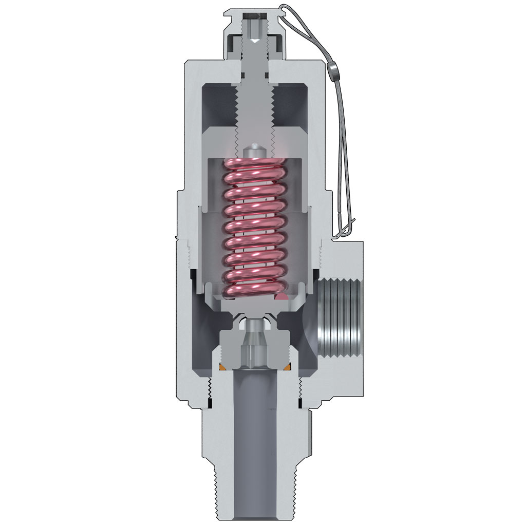
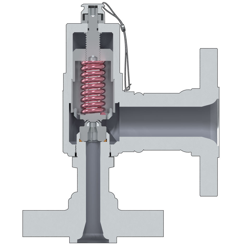
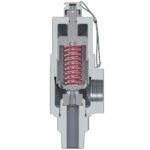
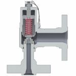
- Designed with “Auto Seat Technology”®
- A low rated and fully guided spring allows for more consistent Set Pressures from pop to pop.
- Consistent Set Pressures allows for repeatable use without the need for excessive repairs or resetting.
- Open, Close, Seat and Seal™
- Fully guided disk for the proper alignment, opening and closing, and reseating of the valve.
- Mechanical Stop prevents wear on parts and controls valve lift.
- Pop Action relief allows the valve to go to full lift at Set Pressure. This helps with DOT regulated applications.
- Non-rising stems allowing valves to be installed in small areas.
- Sour Service Trim available.
- Additional options available to meet NACE MR0175 requirements.
- Canadian Registration Number (CRN)
- Additional options available to meet Conformité Européenne (CE) to PED Directive 2014/68/EU and/or ATEX Directive 2014/34/EU
| Orifice | C (USC) | C (SI) |
|---|---|---|
| OrificeStandard Inlet Connections | C (USC)3/4", 1" | C (SI)DN 20, DN 25 |
| OrificeThreaded Outlet Sizes | C (USC)1" | C (SI)DN 25 |
| OrificeFlanged Outlet Sizes | C (USC)1 ½", 2" | C (SI)DN 40, DN 50 |
| OrificeActual Orifice Diameter | C (USC)0.281 in | C (SI)7.1 mm |
| OrificeActual Orifice Area | C (USC)0.062 in2 | C (SI)40.0 mm2 |
| OrificePressure Range | C (USC)3000 – 8700 psig | C (SI)20684 – 59984 kPa |
| OrificeStandard Temperature Range | C (USC)-20°F to 400°F | C (SI)-29°C to 204°C |
| OrificeASME Flow Coefficient, Kd (Gas) | C (USC)0.818 | C (SI)0.818 |
| OrificeASME Flow Coefficient, Kd (Liquid) | C (USC)0.707 | C (SI)0.707 |
Mercer Valve Co., Inc. reserves the right to change product designs and specifications without notice.
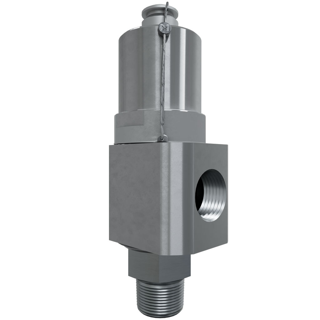
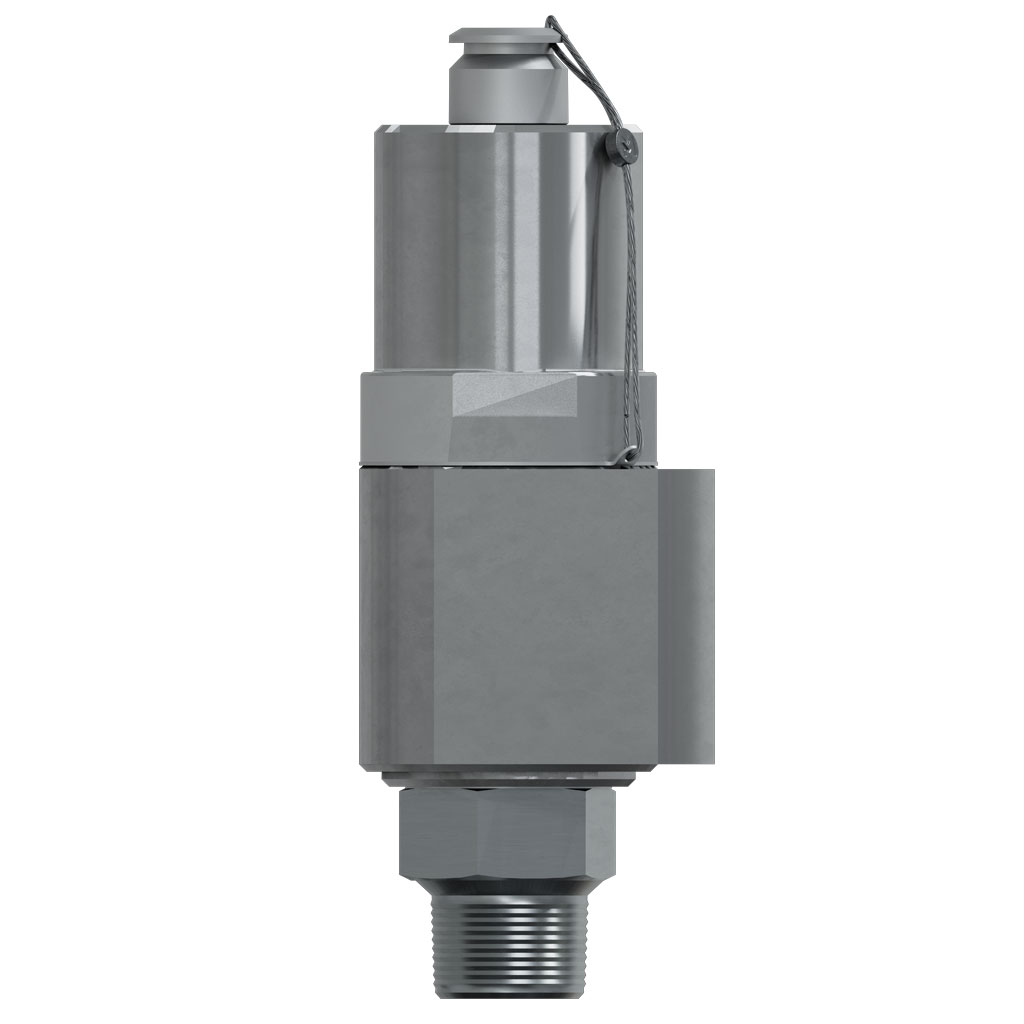
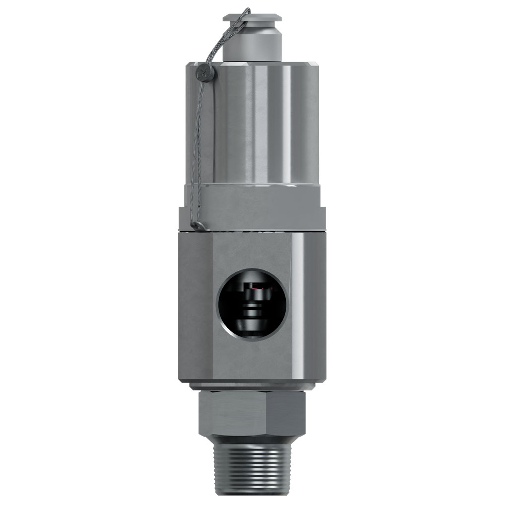
9100 Model 20 "C" Orifice | Part Number Selection
91 -
M7
A
C
B
6
C
1
D
P
E
16
F
4
G
1
H
I
A | INLET & OUTLET COMBINATION
(See Dimensions & Weights, below.)
B | ORIFICE LETTER
C – 0.062 in²
C | THREADED INLET BASE & BODY MATERIAL
6★ – STAINLESS STEEL / CARBON STEEL
7 – STAINLESS STEEL / STAINLESS STEEL
R – STAINLESS STEEL / LF2 CARBON STEEL
C | FLANGE TYPE & BODY MATERIAL
1★ – RF x RF / CARBON STEEL
3★ – RTJ x RF / CARBON STEEL
2 – RF x RF / STAINLESS STEEL
4 – RTJ x RF / STAINLESS STEEL
A – RTJ x RTJ / CARBON STEEL
B – RTJ x RTJ / STAINLESS STEEL
P – RF x RF / LF2 CARBON STEEL
Q – RTJ x RF / LF2 CARBON STEEL
D | CAP TYPE
1★ – CLOSED CAP
2 – OPEN LIFT LEVER
3 – CLOSED LIFT LEVER
E | SEAT MATERIAL
P★ – VIRGIN PEEK
Y – VESPEL®
F | SPRING CODE
(Spring codes assigned by Mercer Valve.)
G | TRIM CODES
4★ – 440C S.S. DISK & NOZZLE (STD GAS SERVICE)
L★ – 316 S.S. DISK & NOZZLE (LIQUID SERVICE, 6200 PSIG MAX)
N★ – 316 S.S. DISK & NOZZLE (SOUR GAS SERVICE, 6200 PSIG MAX)
B★ – 316 S.S. DISK & NOZZLE (SOUR LIQUID SERVICE, 6200 PSIG MAX)
U – 316 S.S. DISK & NOZZLE (OPTIONAL GAS SERVICE, 6200 PSIG MAX)
X – ALL 316 S.S. (OPTIONAL GAS SERVICE)
LX – ALL 316 S.S. (OPTIONAL LIQUID SERVICE, 6200 PSIG MAX)
BX – ALL 316 S.S. (OPTIONAL SOUR LIQUID SERVICE, 6200 PSIG MAX)
NX – ALL 316 S.S. (OPTIONAL SOUR GAS SERVICE, 6200 PSIG MAX)
H | O-RING MATERIAL
1★ – FKM & BUNA-N (STANDARD)
2 – FKM 75 DURO
3 – FKM 90 DURO
4 – BUNA-N 70 DURO
5 – BUNA-N 75 DURO (LOW TEMP)
6 – FFKM 75 DURO
7 – FFKM 90 DURO
9 – NEOPRENE
A – CHEMRAZ®
C – EPDM 80 DURO
D – EPDM 90 DURO
F – PTFE
G – TFE/P
H – SILICONE
J – FLUOROSILICONE
K – HNBR
L – PC BUNA
M – FKM ED
P – FKM 75 DURO (LOW TEMP)
I | TWO-DIGIT "SPECIAL" CODE
(Two-digit special codes assigned by Mercer Valve, if applicable.)
★Standard Materials or Options.
| Inlet and Outlet Code | Inlet and Outlet Size | Pressure Limit1, 2 (psi) | Dimensions2 "A" x "B" x "C" (in ± .062) | Approximate Weight2 (lbs) |
|---|---|---|---|---|
| Inlet and Outlet CodeM1 | Inlet and Outlet Size ¾" FNPT x 1" FNPT | Pressure Limit1, 2 (psi) 8700 | Dimensions2 "A" x "B" x "C" (in ± .062) 2.266 x 1.725 x 7.179 | Approximate Weight2 (lbs) |
| Inlet and Outlet CodeM2★ | Inlet and Outlet Size ¾" MNPT x 1" FNPT | Pressure Limit1, 2 (psi) 8700 | Dimensions2 "A" x "B" x "C" (in ± .062) 3.203 x 1.725 x 8.116 | Approximate Weight2 (lbs)6.5 |
| Inlet and Outlet CodeM5♦ | Inlet and Outlet Size ½" FNPT x 1" FNPT | Pressure Limit1, 2 (psi) 8700 | Dimensions2 "A" x "B" x "C" (in ± .062) 2.266 x 1.725 x 7.179 | Approximate Weight2 (lbs) |
| Inlet and Outlet CodeM6♦ | Inlet and Outlet Size ½" MNPT x 1" FNPT | Pressure Limit1, 2 (psi) 8700 | Dimensions2 "A" x "B" x "C" (in ± .062) 3.203 x 1.725 x 8.116 | Approximate Weight2 (lbs) |
| Inlet and Outlet CodeM7★ | Inlet and Outlet Size 1" MNPT x 1" FNPT | Pressure Limit1, 2 (psi) 8700 | Dimensions2 "A" x "B" x "C" (in ± .062) 3.202 x 1.725 x 8.116 | Approximate Weight2 (lbs)6.5 |
| Inlet and Outlet CodeM8 | Inlet and Outlet Size 1" FNPT x 1" FNPT | Pressure Limit1, 2 (psi) 8700 | Dimensions2 "A" x "B" x "C" (in ± .062) 4.203 x 1.725 x 9.116 | Approximate Weight2 (lbs) |
| Inlet and Outlet Code62 | Inlet and Outlet Size ¾" CODE 62 x 1" FNPT | Pressure Limit1, 2 (psi) 6200 | Dimensions2 "A" x "B" x "C" (in ± .062) 4.203 x 1.725 x 9.116 | Approximate Weight2 (lbs) |
| Inlet and Outlet Code78 | Inlet and Outlet Size 1" 1500 RF x 1½" 300 RF | Pressure Limit1, 2 (psi) 3705 | Dimensions2 "A" x "B" x "C" (in ± .062) 5.000 x 5.250 x 9.913 | Approximate Weight2 (lbs)9 |
| Inlet and Outlet Code76 | Inlet and Outlet Size 1" 2500 RF x 1½" 300 RF | Pressure Limit1, 2 (psi) 6170 | Dimensions2 "A" x "B" x "C" (in ± .062) 5.000 x 5.250 x 9.913 | Approximate Weight2 (lbs)9 |
| Inlet and Outlet Code79 | Inlet and Outlet Size 1" 1500 RF x 2" 300 RF | Pressure Limit1, 2 (psi) 3705 | Dimensions2 "A" x "B" x "C" (in ± .062) | Approximate Weight2 (lbs) |
| Inlet and Outlet Code77 | Inlet and Outlet Size 1" 2500 RF x 2" 300 RF | Pressure Limit1, 2 (psi) 6170 | Dimensions2 "A" x "B" x "C" (in ± .062) 5.000 x 5.250 x 9.913 | Approximate Weight2 (lbs) |
1Pressure limit may be subject to system conditions and temperatures.
2Pressure limit, weight, and “C” dimension may vary with sour gas service and other options.
★Standard Materials or Options.
♦Compressor Service Only.
| Inlet and Outlet Code | Inlet and Outlet Size DN (mm) | Pressure Limit1, 2 (kPa) | Dimensions2 "A" x "B" x "C" (mm ± 1.6) | Approximate Weight2 (kg) |
|---|---|---|---|---|
| Inlet and Outlet CodeM1 | Inlet and Outlet Size DN (mm)DN 20 (FNPT) x DN 25 (FNPT) | Pressure Limit1, 2 (kPa)59984 | Dimensions2 "A" x "B" x "C" (mm ± 1.6)57.7 x 43.9 x 182.4 | Approximate Weight2 (kg) |
| Inlet and Outlet CodeM2★ | Inlet and Outlet Size DN (mm)DN 20 (MNPT) x DN 25 (FNPT) | Pressure Limit1, 2 (kPa)59984 | Dimensions2 "A" x "B" x "C" (mm ± 1.6)81.3 x 43.9 x 206.2 | Approximate Weight2 (kg)2.9 |
| Inlet and Outlet CodeM5♦ | Inlet and Outlet Size DN (mm)DN 15 (FNPT) x DN 25 (FNPT) | Pressure Limit1, 2 (kPa)59984 | Dimensions2 "A" x "B" x "C" (mm ± 1.6)57.7 x 43.9 x 182.4 | Approximate Weight2 (kg) |
| Inlet and Outlet CodeM6♦ | Inlet and Outlet Size DN (mm)DN 15 (MNPT) x DN 25 (FNPT) | Pressure Limit1, 2 (kPa)59984 | Dimensions2 "A" x "B" x "C" (mm ± 1.6)81.3 x 43.9 x 206.2 | Approximate Weight2 (kg) |
| Inlet and Outlet CodeM7★ | Inlet and Outlet Size DN (mm)DN 25 (MNPT) x DN 25 (FNPT) | Pressure Limit1, 2 (kPa)59984 | Dimensions2 "A" x "B" x "C" (mm ± 1.6)81.3 x 43.9 x 206.2 | Approximate Weight2 (kg)2.9 |
| Inlet and Outlet CodeM8 | Inlet and Outlet Size DN (mm)DN 25 (FNPT) x DN 25 (FNPT) | Pressure Limit1, 2 (kPa)59984 | Dimensions2 "A" x "B" x "C" (mm ± 1.6)81.3 x 43.9 x 206.2 | Approximate Weight2 (kg) |
| Inlet and Outlet Code62 | Inlet and Outlet Size DN (mm)DN 20 CODE 62 x DN 25 (FNPT) | Pressure Limit1, 2 (kPa)42747 | Dimensions2 "A" x "B" x "C" (mm ± 1.6)106.7 x 43.9 x 251.7 | Approximate Weight2 (kg) |
| Inlet and Outlet Code78 | Inlet and Outlet Size DN (mm)DN 25 1500 x DN 40 300 | Pressure Limit1, 2 (kPa)25545 | Dimensions2 "A" x "B" x "C" (mm ± 1.6)127.0 x 133.4 x 251.7 | Approximate Weight2 (kg)4.1 |
| Inlet and Outlet Code76 | Inlet and Outlet Size DN (mm)DN 25 2500 x DN 40 300 | Pressure Limit1, 2 (kPa)42540 | Dimensions2 "A" x "B" x "C" (mm ± 1.6)127.0 x 133.4 x 251.7 | Approximate Weight2 (kg)4.1 |
| Inlet and Outlet Code79 | Inlet and Outlet Size DN (mm)DN 25 1500 x DN 50 300 | Pressure Limit1, 2 (kPa)25545 | Dimensions2 "A" x "B" x "C" (mm ± 1.6) | Approximate Weight2 (kg) |
| Inlet and Outlet Code77 | Inlet and Outlet Size DN (mm)DN 25 2500 x DN 50 300 | Pressure Limit1, 2 (kPa)42540 | Dimensions2 "A" x "B" x "C" (mm ± 1.6)127.0 x 133.4 x 251.7 | Approximate Weight2 (kg) |
1Pressure limit may be subject to system conditions and temperatures.
2Pressure limit, weight, and “C” dimension may vary with sour gas service and other options.
★Standard Materials or Options.
♦Compressor Service Only.