
think…mercer first®
Features:
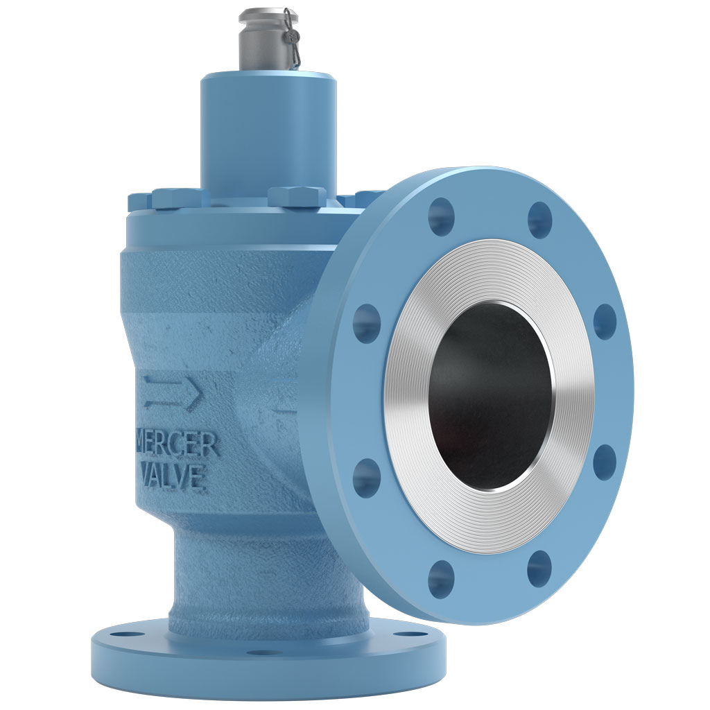
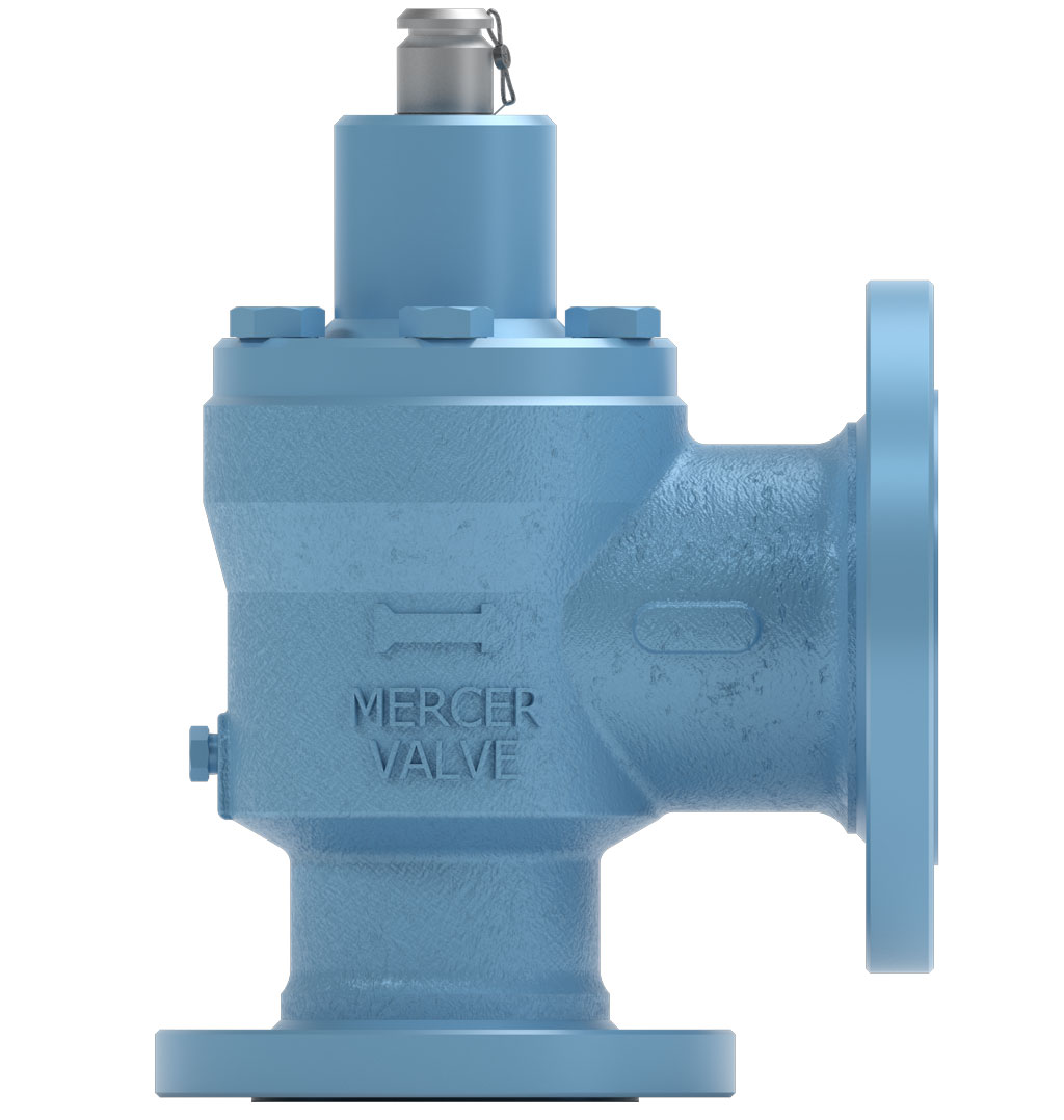
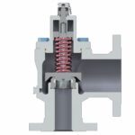
- Designed with "Auto Seat Technology"®
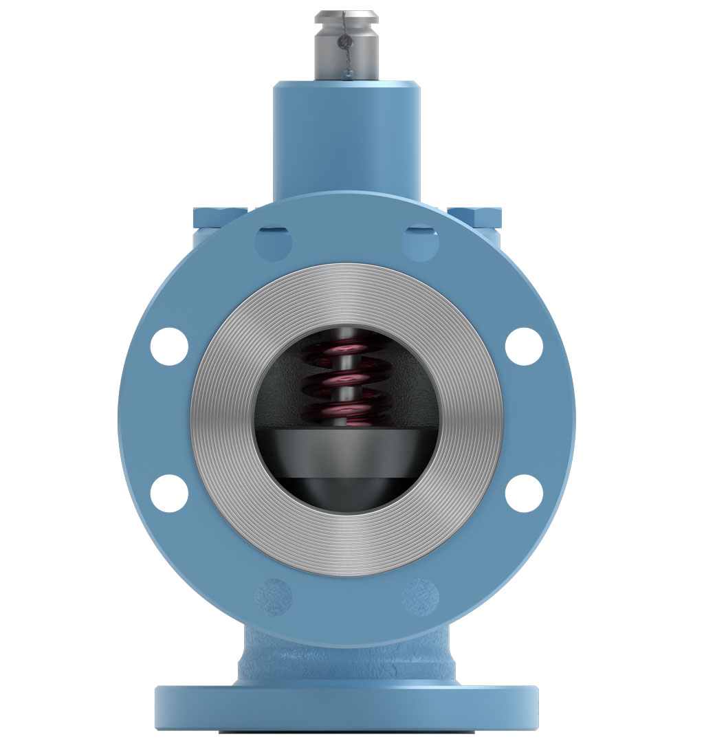
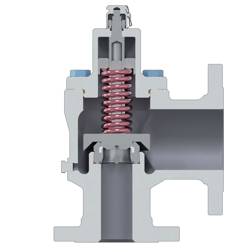
- A low rated and fully guided spring allows for more consistent Set Pressures from pop to pop.
- Consistent Set Pressures allows for repeatable use without the need for excessive repairs or resetting.
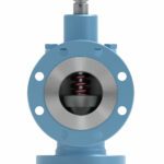
- Open, Close, Seat and Seal™
- Fully guided disk for the proper alignment, opening and closing, and reseating of the valve.
- Mechanical Stop prevents wear on parts and controls valve lift.
- Pop Action relief allows the valve to go to full lift at Set Pressure. This helps with DOT regulated applications.
- Non-rising stems allowing valves to be installed in small areas.
- Sour Service Trim available.
- Additional options available to meet NACE MR0175 requirements.
- Canadian Registration Number (CRN)
- Additional options available to meet Conformité Européenne (CE) to PED Directive 2014/68/EU and/or ATEX Directive 2014/34/EU
| Orifice | J
(USC) | J
(SI) |
|---|---|---|
| OrificeStandard Inlet Sizes | J
(USC) 2", 3" | J
(SI) DN 40, DN 80 |
| OrificeInlet and Outlet Connection Types | J
(USC) RF x RF, RTJ x RF, RTJ x RTJ | J
(SI) RF x RF, RTJ x RF, RTJ x RTJ |
| OrificeActual Orifice Diameter | J
(USC) 1.350 in | J
(SI) 34.3 mm |
| OrificeActual Orifice Area | J
(USC) 1.430 in2 | J
(SI) 922.6 mm2 |
| OrificeAPI Orifice Area | J
(USC) 1.287 in2 | J
(SI) 830.3 mm2 |
| OrificePressure Range | J
(USC) 10 – 1800 psig | J
(SI) 68 – 12410 kPa |
| OrificeStandard Temperature Range | J
(USC) -20°F to 400°F | J
(SI) -29°C to 204°C |
| OrificeASME Flow Coefficient, Kd (Gas) | J
(USC) 0.818 | J
(SI) 0.818 |
| OrificeASME Flow Coefficient, Kd (Liquid) | J
(USC) 0.707 | J
(SI) 0.707 |
Mercer Valve Co., Inc. reserves the right to change product designs and specifications without notice.
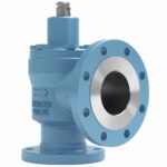
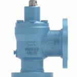
9100 Flanged "J" | Part Number Selection
91 -
62
A
J
B
1
C
1
D
T
E
84
F
U
G
1
H
I
A | INLET & OUTLET COMBINATION
(See Dimensions & Weights, below.)
B | API ORIFICE LETTER
J – 1.430 in²
C | INLET & OUTLET TYPE / BODY MATERIAL
1★ – RF x RF / WCB CARBON STEEL
3★ – RTJ x RF / WCB CARBON STEEL
2 – RF x RF / CF3M STAINLESS STEEL
4 – RTJ x RF / CF3M STAINLESS STEEL
A – RTJ x RTJ / WCB CARBON STEEL
B – RTJ x RTJ / CF3M STAINLESS STEEL
P – RF x RF / LCC TEMP CARBON STEEL
Q – RTJ x RF / LCC TEMP CARBON STEEL
D | CAP TYPE
1★ – CLOSED CAP
2 – OPEN LIFT LEVER
3 – CLOSED LIFT LEVER
E | SEAT MATERIAL
V★ – FKM
T★ – PTFE
P★ – VIRGIN PEEK
B – BUNA-N
E – EPDM
N – NEOPRENE
Y – VESPEL®
L – PC BUNA
F – FKM (LOW TEMP)
F | SPRING CODE
(Spring codes assigned by Mercer Valve.)
G | TRIM CODES
U★ – 316 S.S. DISK & NOZZLE (GAS SERVICE ≤ 1125 PSIG)
C★ – 440C S.S. DISK, 17-4 S.S. NOZZLE (GAS SERVICE > 1125 PSIG)
L★ – 316 S.S. DISK & NOZZLE (LIQUID SERVICE)
N★ – 316 S.S. DISK & NOZZLE (SOUR GAS SERVICE)
B★ – 316 S.S. DISK & NOZZLE (SOUR LIQUID SERVICE)
X – ALL 316 S.S. (OPTIONAL GAS SERVICE)
LX – ALL 316 S.S. (OPTIONAL LIQUID SERVICE)
BX – ALL 316 S.S. (OPTIONAL SOUR LIQUID SERVICE)
NX – ALL 316 S.S. (OPTIONAL SOUR GAS SERVICE)
H | O-RING MATERIAL
1★ – FKM & BUNA-N (STANDARD)
2 – FKM 75 DURO
3 – FKM 90 DURO
4 – BUNA-N 70 DURO
5 – BUNA-N 75 DURO (LOW TEMP)
7 – FFKM
9 – NEOPRENE
A – CHEMRAZ®
C – EPDM 80 DURO
D – EPDM 90 DURO
G – TFE/P
H – SILICONE
J – FLUOROSILICONE
K – HNBR
L – PC BUNA
M – FKM ED
P – FKM 75 DURO (LOW TEMP)
I | TWO-DIGIT "SPECIAL" CODE
(Two-digit special codes assigned by Mercer Valve, if applicable.)
★Standard Materials or Options.
| Inlet and Outlet Code | Inlet and Outlet Size (in) | Pressure Limit 1, 2 (psig) | Dimensions 2
"A" x "B" x "C" (in ± .062) | Approximate Weight 2 (lbs) |
|---|---|---|---|---|
| Inlet and Outlet Code51★☆ | Inlet and Outlet Size (in) 2" 150 x 3" 150 | Pressure Limit 1, 2 (psig) 285 | Dimensions 2
"A" x "B" x "C" (in ± .062) 5.375 x 4.875 x 13.375 | Approximate Weight 2 (lbs) 52 |
| Inlet and Outlet Code52★ | Inlet and Outlet Size (in) 2" 300 x 3" 150 | Pressure Limit 1, 2 (psig) 740 | Dimensions 2
"A" x "B" x "C" (in ± .062) 5.375 x 4.875 x 13.375 | Approximate Weight 2 (lbs) 65 |
| Inlet and Outlet Code53 | Inlet and Outlet Size (in) 2" 600 x 3" 150 | Pressure Limit 1, 2 (psig) 850 | Dimensions 2
"A" x "B" x "C" (in ± .062) 5.375 x 4.875 x 13.375 | Approximate Weight 2 (lbs) |
| Inlet and Outlet Code91 | Inlet and Outlet Size (in) 2" 900 x 3" 150 | Pressure Limit 1, 2 (psig) 850 | Dimensions 2
"A" x "B" x "C" (in ± .062) 6.563 x 6.750 x 14.563 | Approximate Weight 2 (lbs) |
| Inlet and Outlet Code57 | Inlet and Outlet Size (in) 2 ½" 300 x 4" 150 | Pressure Limit 1, 2 (psig) 740 | Dimensions 2
"A" x "B" x "C" (in ± .062) 5.375 x 5.625 x 13.375 | Approximate Weight 2 (lbs) |
| Inlet and Outlet Code58 | Inlet and Outlet Size (in) 2 ½" 600 x 4" 150 | Pressure Limit 1, 2 (psig) 1480 | Dimensions 2
"A" x "B" x "C" (in ± .062) 6.125 x 6.750 x 14.125 | Approximate Weight 2 (lbs) |
| Inlet and Outlet Code62★ | Inlet and Outlet Size (in) 3" 150 x 4" 150 | Pressure Limit 1, 2 (psig) 285 | Dimensions 2
"A" x "B" x "C" (in ± .062) 6.125 x 6.375 x 14.125 | Approximate Weight 2 (lbs) 76 |
| Inlet and Outlet Code84★☆ | Inlet and Outlet Size (in) 3" 300 x 4" 150 | Pressure Limit 1, 2 (psig) 740 | Dimensions 2
"A" x "B" x "C" (in ± .062) 7.250 x 7.125 x 15.250 | Approximate Weight 2 (lbs) 94 |
| Inlet and Outlet Code85★☆ | Inlet and Outlet Size (in) 3" 600 x 4" 150 | Pressure Limit 1, 2 (psig) 1480 | Dimensions 2
"A" x "B" x "C" (in ± .062) 7.250 x 7.125 x 15.250 | Approximate Weight 2 (lbs) 96 |
| Inlet and Outlet Code86★☆ | Inlet and Outlet Size (in) 3" 900 x 4" 150 | Pressure Limit 1, 2 (psig) 1800 | Dimensions 2
"A" x "B" x "C" (in ± .062) 7.250 x 7.125 x 15.250 | Approximate Weight 2 (lbs) 107 |
1Pressure limit may be subject to system conditions and temperatures.
2Pressure limit, weight, and “C” dimension may vary with sour gas service and other options.
★Standard Materials or Options.
☆Flange dimensions compliant with API 526.
| Inlet and Outlet Code | Inlet and Outlet Size DN (mm) | Pressure Limit 1, 2 (kPa) | Dimensions 2 "A" x "B" x "C" (mm ± 1.6) | Approximate Weight (kg) |
|---|---|---|---|---|
| Inlet and Outlet Code51★☆ | Inlet and Outlet Size DN (mm)DN 50 150 x DN 80 150 | Pressure Limit 1, 2 (kPa)1965 | Dimensions 2 "A" x "B" x "C" (mm ± 1.6)136.5 x 123.8 x 339.7 | Approximate Weight (kg)23.6 |
| Inlet and Outlet Code52★ | Inlet and Outlet Size DN (mm)DN 50 300 x DN 80 150 | Pressure Limit 1, 2 (kPa)5102 | Dimensions 2 "A" x "B" x "C" (mm ± 1.6)136.5 x 123.8 x 433.4 | Approximate Weight (kg)29.5 |
| Inlet and Outlet Code53 | Inlet and Outlet Size DN (mm)DN 50 600 x DN 80 150 | Pressure Limit 1, 2 (kPa)5860 | Dimensions 2 "A" x "B" x "C" (mm ± 1.6)136.5 x 123.8 x 433.4 | Approximate Weight (kg) |
| Inlet and Outlet Code91 | Inlet and Outlet Size DN (mm)DN 50 900 x DN 80 150 | Pressure Limit 1, 2 (kPa)5860 | Dimensions 2 "A" x "B" x "C" (mm ± 1.6)166.7 x 171.5 x 369.9 | Approximate Weight (kg) |
| Inlet and Outlet Code57 | Inlet and Outlet Size DN (mm)DN 65 300 x DN 100 150 | Pressure Limit 1, 2 (kPa)5102 | Dimensions 2 "A" x "B" x "C" (mm ± 1.6)136.5 x 142.9 x 339.7 | Approximate Weight (kg) |
| Inlet and Outlet Code58 | Inlet and Outlet Size DN (mm)DN 65 600 x DN 100 150 | Pressure Limit 1, 2 (kPa)10204 | Dimensions 2 "A" x "B" x "C" (mm ± 1.6)155.6 x 171.5 x 358.8 | Approximate Weight (kg) |
| Inlet and Outlet Code62★ | Inlet and Outlet Size DN (mm)DN 80 150 x DN 100 150 | Pressure Limit 1, 2 (kPa)1965 | Dimensions 2 "A" x "B" x "C" (mm ± 1.6)155.6 x 161.9 x 358.8 | Approximate Weight (kg)34.5 |
| Inlet and Outlet Code84★☆ | Inlet and Outlet Size DN (mm)DN 80 300 x DN 100 150 | Pressure Limit 1, 2 (kPa)5102 | Dimensions 2 "A" x "B" x "C" (mm ± 1.6)184.2 x 181.0 x 387.4 | Approximate Weight (kg)42.6 |
| Inlet and Outlet Code85★☆ | Inlet and Outlet Size DN (mm)DN 80 600 x DN 100 150 | Pressure Limit 1, 2 (kPa)10204 | Dimensions 2 "A" x "B" x "C" (mm ± 1.6)184.2 x 181.0 x 387.4 | Approximate Weight (kg)43.5 |
| Inlet and Outlet Code86★☆ | Inlet and Outlet Size DN (mm)DN 80 900 x DN 100 150 | Pressure Limit 1, 2 (kPa)12410 | Dimensions 2 "A" x "B" x "C" (mm ± 1.6)184.2 x 181.0 x 387.4 | Approximate Weight (kg)48.5 |
1Pressure limit may be subject to system conditions and temperatures.
2Pressure limit, weight, and “C” dimension may vary with sour gas service and other options.
★Standard Materials or Options.
☆Flange dimensions compliant with API 526.